|
|
|
Who's Online
There currently are 5639 guests online. |
|
Categories
|
|
Information
|
|
Featured Product
|
|
|
 |
|
|
There are currently no product reviews.
 ;
Well done!!! I found what I need to have, indeed!
Furthermore, due to my hobby is repairing vintage equipments, I added this web site in my desk toolbar because I have in mind to search further service manuals. Thanks a lot www.owner-manuals.com !
Regards, Maurizio
;
Again very good service manual, this time very fast download. AAAAA+
;
Ckear manual, well reproduced with plenty of overlap on critical pages.
;
I buy the service manual cheaper here than in elsewhere.Am happy with this site. I recommended the Owner-Manuals.com
;
Great Manual. It was exactly what I was looking for
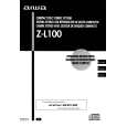
B FRONT C.B
16
TP7 (K-SCAN) FL201
D-GND
IC101
L101
SFR701
10
DECK�1 R/P/E, DECK-2 P HEAD
11
11
< DECK SECTION >
10. Tape Speed Adjustment (DECK 1) Settings : � Test tape : TTA�100 � Test point : TP8 (Lch), TP9 (Rch) � Adjustment location : SFR701 Method : Play back the test tape and adjust SFR701 so that the frequency counter reads 3000Hz ± 5Hz. 11. Head Azimuth Adjustment (DECK 1, DECK 2) Settings : � Test tape : TTA�330 � Test point : TP8 (Lch), TP9 (Rch) � Adjustment location : Head azimuth adjustment screw Method : Play back (FWD) the 8kHz signal of the test tape and adjust screw so that the output becomes maximum. 12. PB Frequency Response Check (DECK 1, DECK 2) Settings : � Test tape : TTA�330 � Test point :TP8 (Lch), TP9 (Rch) Method : Play back the 315Hz and 8kHz signals of the test tape and check that the output ratio of the 8kHz signal with respect to that of the 315Hz signal is within 5dB. 13. PB Sensitivity Check (DECK 1, DECK 2) Settings : � Test tape : TTA�200 � Test point : TP8 (Lch), TP9 (Rch) Method : Play back the test tape and check that the output level of the test point is 140mV ± 3dB. 14. REC/PB Frequency Response Adjustment (DECK 1) Settings : � Test tape : TTA�602 � Test point : TP8 (Lch), TP9 (Rch) � Input signal : 1kHz / 8kHz (LINE IN) � Adjustment location : SFR451 (Lch) SFR452 (Rch) Method : Apply a 1kHz signal and REC mode. Then adjust OSC attenuator so that the output level at the TP8, TP9 becomes -20VU (9~11mV). Record and play back the 1kHz and 8kHz signals and adjust SFRs so that the output of the 8kHz signals becomes 0dB ± 0.5dB with respect to that of the 1kHz signal. 15. REC/PB Sensitivity Check (DECK 1) Settings : � Test tape : TTA�602 � Test point : TP8 (Lch), TP9 (Rch) � Input signal : 1kHz (LINE IN) Method : Apply a 1kHz signal and REC mode. Then adjust OSC attenuator so that the output level at TP8, TP9 becomes 0VU (90~110mV). Record and play back the 1kHz signals and check that the output is 0dB ± 3.0dB.
< FRONT SECTION >
16. MICON OSC Adjustment Settings : � Test point : TP7 (K-SCAN) and D-GND � Adjustment location : L101 Method : Pull out AC plug, then insert AC plug again with pressing of TUNER function key and POWER key. Adjust L101 so that the frequency across the test point is 58.3525Hz ± 0.058Hz or 17.1372ms ± 0.017ms.
� 23 �
 $4.99 ZL100 AIWA
Owner's Manual Complete owner's manual in digital format. The manual will be available for download as PDF file aft…
|
|
|
> |
|